AT&T PC6300 connector pinout |
layout |
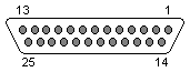 25 pin D-SUB FEMALE connector |
Monochrome monitor: ID0 and ID1 are open
| 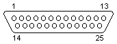 25 pin D-SUB MALE connector | ||||||||||||||||||||||||||||||||||||||||||||||||||||||||||||||||||||||||||||
Pinouts.ru > Pinouts of video connectors > Pinout of AT&T PC6300 connector and layout of 25 pin D-SUB FEMALE connector and 25 pin D-SUB MALE connector Source(s): Tommy"s pinout Collection by Tommy Johnson, from Hardware Book | unknown | |
|
mark as correct |
0 report(s) | |
| Click one of this links to change document status. | ||