Apple ATA connector pinout |
layout |
The internal hard disk has a 48-pin connector that carries both the ATA signals and the power for the drive.
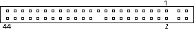 48 pin Apple ATA connector at the Apple computer | The connector has the dimensions of a 50-pin connector, but with one row of pins removed. The remaining pins are in two groups: pins 1–44, which carry the signals and power, and pins 45–48, which are reserved.
/DA(0–2) Device address; used by the computer to select one of the registers in the ATA drive. For more information, see the descriptions of the CS0 and CS1 signals. DD(0–15) Data bus; buffered from IOD(16–31) of the computer’s I/O bus. DD(0–15) are used to transfer 16-bit data to and from the drive buffer. DD(8–15) are used to transfer data to and from the internal registers of the drive, with DD(0–7) driven high when writing. /CBLID The host checks this signal after Power On or hardware reset to detect whether an 80-conductor cable is present. /CS0 Register select signal. It is asserted low to select the main task file registers. The task file registers indicate the command, the sector address, and the sector count. /CS1 Register select signal. It is asserted low to select the additional control and status registers on the ATA drive. CSEL Cable select; not available on the iBook. /DASP Device active or slave present; not available on the iBook. /DDMARDY Drive ready to receive Ultra DMA data. /DIOR I/O data read strobe. /DIOW I/O data write strobe. /DMACK Used by the host to initiate a DMA transfer in response to DMARQ. DSTROBE Strobe for Ultra DMA data transfers to host. /HDMARDY Ultra DMA data ready. HSTROBE Strobe for Ultra DMA data transfers from host. IORDY I/O ready; when driven low by the drive, signals the CPU to insert wait states into the I/O read or write cycles. /IOCS16 I/O channel select; not used on this computer (pulled low by 1 kilohm resistor). DMARQ Asserted by the device when it is ready to transfer data to or from the host. INTRQ Interrupt request. This active high signal is used to inform the computer that a data transfer is requested or that a command has terminated. /PDIAG Asserted by device 1 to indicate to device 0 that it has completed the power-on diagnostics; not available on the iBook. /RESET Hardware reset to the drive; an active low signal. /STOP Stop request; an active low signal. Key This pin is the key for the connector.
| ||||||||||||||||||||||||||||||||||||||||||||||||||||||||||||||||||||||||||||||||||||||||||||||||||||||||||||||||||||||||||||||||||||||||||||||||||||||||||||||||||||||||||||||||||||||
Pinouts.ru > Pinouts of different harddrives connectors > Pinout of Apple ATA connector and layout of 48 pin Apple ATA connector Source(s): Apple iBook developer note | unknown | |
|
mark as correct |
0 report(s) | |
| Click one of this links to change document status. | ||