Pinouts of Connectors

Commodore 64 / 128 User I/O pinout

layout
schematic diagram

add this page to bookmarks

24 pin DZM 12 DREH connector pin-out & layout
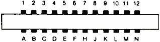
24 pin DZM 12 DREH connector  at the computer

Top side

1 GND Ground
2 +5VDC (100 mA max)
3 /RESET Reset, will force a Cold Start. Also a reset output for devices.
4 CNT1 Serial port counter from CIA #1
5 SP1 Serial port from CIA #1
6 CNT2 Serial port counter from CIA #2
7 SP2 Serial port from CIA #2
8 /PC2 Handshaking line from CIA #2
9 ATN This pin is connected to the ATN line of the serial bus
10 +9VAC (+ phase) Connected directly to the Commodore 64 transformer (100 mA max)
11 +9VAC (- phase) Connected directly to the Commodore 64 transformer (100 mA max)
12 GND Ground

Bottom side

A GND Ground
B /FLAG2 The Commodore 64 gives you complete control over Port B on VIA chip #1. Eight lines for input or output are available, as well as 2 lines for handshaking with an outside device. The I/O lines for Port B are controlled by two locations. One is the port itself, and is located at 56577 ($DD01 hex). Naturally you PEEK it to read an input, or POKE it to set an output. Each of the eight I/O lines can be set up as either an input or an output by setting the data direction register properly. It is located at 56579 ($DD03 hex).
C PB0
D PB1
E PB2
F PB3
H PB4
J PB5
K PB6
L PB7
M PA2
N GND Ground

This information should be correct, but may be not. You can help us to improve this webpage!
You can confirm this document to be correct (be careful), or report an error in document (error may be described in the following webpage). Result of your submission will be used for calculating document status shown at the bottom of this page.
Pinouts.ru > Pinouts of different motherboard slots >  Pinout of Commodore 64 / 128 User I/O and layout of 24 pin DZM 12 DREH connector

Source(s): Commodore 64 User Manual, Commodore 64 Programmer"s Reference Guide
Document status: unknown
mark as erroneous!
mark as correct
0 report(s)
Click one of this links to change document status.
[Discuss at the forum] [Back to index] [Add new pinout]
[Report an error or update]
This information is maintained by pinouts.ru team and provided as a guideline only.
Efforts have been made to ensure it is correct, but it is the responsibility of the user
to verify the data is correct for their application.
70 hits since February 12, 2005