IEEE1394 connector pinout |
layout |
Full name IEEE 1394-1995. Also known as FireWire (Apple), iLink (Sony) or Lynx. Defines a serial data transfer protocol and interconnection system.
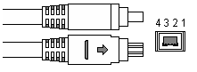 4 pin IEEE1394 FEMALE connector at the devices | The IEEE 1394-1995 standard for the High Performance Serial Bus defines a serial data transfer protocol. 1394 incorporates quite advanced technology, but it"s the "much lower cost" feature that assures 1394"s adoption for the digital video and audio consumer markets of 1997 and beyond. IEEE 1394 is going to be the interface for connecting handy-cams and VCRs, settop boxes and televisions. The capabilities of the 1394 bus are sufficient to support a variety of high-end digital audio/video applications, such as consumer audio/video device control and signal routing, home networking, nonlinear DV editing, and 32-channel (or more) digital audio mixing.
1394 is based on Apple Computer"s original 1394 bus, which was intended as a low-cost replacement for or supplement to the SCSI bus that is a standard feature of Macintosh and PowerMac computers. Apple and SGS Thomson, which has an UK patent applicable to 1394, license their patents "on reasonable and non-discriminatory terms to anyone wishing to obtain a license." These licenses apply only to the point of first implementation, which means integrated circuits to implement 1394 connectivity, and thus are of no concern to most adapter card manufacturers or end users. IEEE - 1394 Architecture The 1394 standard defines two bus categories: backplane and cable. The backplane bus is designed to supplement parallel bus structures by providing an alternate serial communication path between devices plugged into the backplane. The cable bus, which is the subject of this paper, is a "non-cyclic network with finite branches," consisting of bus bridges and nodes (cable devices). Non-cyclic meansthat you can"t plug devices together so as to create loops. 16-bit addressing provide for up to 64K nodes in a system. Up to 16 cable hops are allowed between nodes, thus the term finite branches. A bus bridge serves to connect busses of similar or different types; a 1394-to-PCI interface within a PC constitutes a bus bridge, which ordinarily serves as the root device and provides bus master (controller) capability. A bus bridge also would be used to interconnect a 1394 cable and a 1394 backplane bus. Six-bit Node_IDs allow up to 63 nodes to be connected to a single bus bridge; 10 bit Bus_IDs accommodate up to 1,023 bridges in a system. This means, as an example, that the limit is 63 devices connected to a conventional 1394 adapter card in a PC. Each node usually has three connectors, although the standard provides for 1 to 27 connector per a device"s physical layer or PHY. Up to 16 nodes can be daisy-chained through the connectors with standard cables up to 4.5 m in length for a total standard cable length of 72 m. (Using higher-quality "fatter" cables permits longer interconnections.) 1394 truly qualifies as a plug-and-play bus. The 1394 cable standard defines three signaling rates: 98.304, 196.608, and 393.216 Mbps (megabits per second; MBps in this paper refers to megabytes per second.) These rates are rounded to 100, 200, and 400 Mbps, respectively, in this paper and are referred to in the 1394 standard as S100, S200 and S400. Consumer DV gear uses S100 speeds, but most 1394 PC adapter cards support the S200 rate. The signaling rate for the entire bus ordinarily is governed by the slowest active node; however, if a bus master (controller) implements a Topology_Map and a Speed_Map for specific node pairs, the bus can support multiple signaling speeds between individual pairs. Physical, Link, and Transaction Layers The 1394 protocol is implemented by the three stacked layers. The three layers perform the following functions:
Cables and Connectors Standard bus interconnections are made with a 6-conductor cable containing two separately-shielded twisted pair transmission lines for signaling, two power conductors, and an overall shield. The two twisted pairs are crossed in each cable assembly to create a transmit-receive connection. The power conductors (8 to 40 v, 1.5 a max.) supply power to the physical layer in isolated devices. Transformer or capacitative coupling is used to provide galvanic isolation; transformer coupling provides 500 volts and lower-cost capacitative coupling offers 60 volts of ground potential difference isolation. Connectors are derived from the GameBoy design. IEEE-1394Bus Management 1394 provides a flexible bus management system that provides connectivity between a wide range of devices, which need not include a PC or other bus controller. Bus management involves the following three services:
On bus reset, the structure of the bus is determined, node IDs (physical addresses) are assigned to each node, and arbitration for cycle master, isochronous resource manager, and bus master nodes occurs. Isochronous Data Transport The isochronous data transport of the 1394 bus provides the guaranteed bandwidth and latency required for high-speed data transfer over multiple channels. On bus reset or when an isochronous node is added to the bus, the node requests a bandwidth allocation. If adequate bandwidth is not available, the requesting device is expected to repeat its request periodically. Video acquisition for non-linear digital editing is simpler than the camcorder-DVCR example, because it requires only a single isochronous channel, plus an asynchronous path for device control. EEE 1394 is a standard, platform-independent solution. Its features represent an evolutionary improvement over current I/O interfaces and provide connectivity solutions for many markets. Legacy I/O bridges attach serial and parallel interfaces to 1394. ANSI SCSI-3 provides a migration path for parallel SCSI to move to IEEE 1394. IEEE 1394 can interface with the higher layers of the new parallel port standard, IEEE 1284. Although IEEE 1284"s 4 to 32 Mbps transfer rate is lower than that of 1394, 1284 finds application in printer connectivity since it is backward compatible with the existing Centronics parallel port. IEEE 1394 devices of differing transport rates may be interconnected, allowing backward compatibility with devices having slower transport rates. This feature allows 100 Mbps devices purchased today to operate properly in future bus configurations involving 200 and 400 Mbps devices.
| 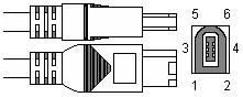 6 pin IEEE1394 FEMALE connector at the devices | |||||||||||||||||||||||||
Pinouts.ru > Pinouts of different motherboard slots > Pinout of IEEE1394 connector and layout of 4 pin IEEE1394 FEMALE connector and 6 pin IEEE1394 FEMALE connector Source(s): Technick.net and others | unknown | |
|
mark as correct |
0 report(s) | |
| Click one of this links to change document status. | ||