Pinouts of Connectors

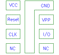
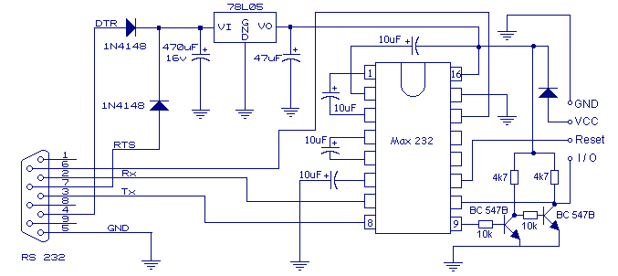
Motorola Sim Card Emulator pinout

layout
schematic diagram

add this page to bookmarks

Motorola service card emulator

9 pin D-SUB MALE connector pin-out & layout
9 pin D-SUB MALE connector  to the computer

Pin Name Function in/out
1 VCC Supply voltage +5 V out
2 Reset Reset (active low)
3 CLK Clock
4 NC NOT USED
5 NC NOT USED
6 I / O DATA INPUT OUTPUT in/out
7 VPP TIRED EVER TO +5V  
8 GND Ground  

This information should be correct, but may be not. You can help us to improve this webpage!
You can confirm this document to be correct (be careful), or report an error in document (error may be described in the following webpage). Result of your submission will be used for calculating document status shown at the bottom of this page.
8 pin SMARTCARD special connector pin-outs & layouts
8 pin SMARTCARD special connector  to the cellular phone (numbering wrong)
Pinouts.ru > Pinouts and schemes of cellular phones cables >  Pinout of Motorola Sim Card Emulator and layout of 9 pin D-SUB MALE connector and 8 pin SMARTCARD special connector

Source(s): Misiek website
Document status: unknown
mark as erroneous!
mark as correct
0 report(s)
Click one of this links to change document status.
[Discuss at the forum] [Back to index] [Add new pinout]
[Report an error or update]
This information is maintained by pinouts.ru team and provided as a guideline only.
Efforts have been made to ensure it is correct, but it is the responsibility of the user
to verify the data is correct for their application.
193 hits since February 12, 2005