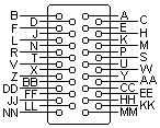
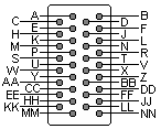
ITU-TSS V.35 connector pinout |
layout |
Basically, V.35 is a high-speed serial interface designed to support both higher data rates and connectivity between DTEs or DCEs over digital lines.
 34 pin M/34 MALE connector | V.35 is an interface (V.35 is the ITU - formerly CCITT standard termed "Data Transmission at 48 Kbps Using 60-108 KHz Group-Band Circuits") commonly used on higher speed circuits of 56kbps and above. Recognizable by its blocky, 34-pin connector; V.35 combines the bandwidth of several telephone circuits to provide the high-speed interface between a DTE or DCE and a CSU/DSU (Channel Service Unit/Data Service Unit). To achieve such high speeds and great distances, V.35 combines both balanced and unbalanced voltage signals on the same interface. Transmission is usually a synchronous protocol (note clocking pins i.e. receive and transmit clock). Although V.35 is commonly used to support speeds ranging anywhere from 48 to 64 Kbps, much higher rates are possible [ ISDN (64 or 128Kbps), Factional T1@ 128 Kbps to 1.544Mbps T1, ATM and Frame Relay]. V.35 cable distances theoretically can range up to 4000 feet (1200 m) at speeds up to 100 Kbps. Actual distances will depend on your equipment and the quality of the cable . Lan routers often come equipped with a V.35 electrical interface but many today are using a HSSI interface at speeds higher than T1 and above (typical T3 45Mbps).
V.35 cable is balanced multipair with characteristic impedance 80-120 Om at the fundamental frequency. There seem to be two versions of the V.35 pinning. One is called V.35 Winchester, the other is called V.35 Straight. One is mirrored to the other. We don"t know how it is mirrored. This information came from a 3Com source. Their Access Builder 4000 V.35 Card interface is V.35 Straight they say. The Dutch PTT supplies V.35 interface according to V.35 Winchester. Connecting these two requires some sort of crossed cable. Note: Direction is DTE (Computer) relative DCE (Modem)
|  34 pin M/34 FEMALE connector | |||||||||||||||||||||||||||||||||||||||||||||||||||||||||||||||||||||||||||||||||||||||||||||||||||||||||||||||||||||||||||||||||||||||||||||
Pinouts.ru > Pinouts of serial ports > Pinout of ITU-TSS V.35 connector and layout of 34 pin M/34 MALE connector and 34 pin M/34 FEMALE connector Source(s): V.35 Page at Connectivity Knowledge Platform (Made IT) | unknown | |
|
mark as correct |
0 report(s) | |
| Click one of this links to change document status. | ||