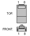
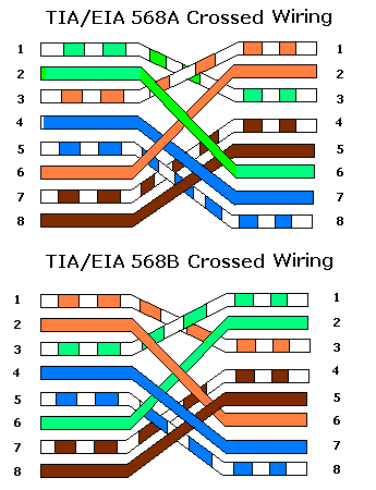
Ethernet 100Base-T4 Crossover cable pinout |
layout |
This cable can be used to connect two computers together without a hub, or to connect two hubs together (without using an uplink port). If you´re connecting two hubs together and one of them has an uplink port, use a straight cable.
 8 pin RJ45 MALE connector to the network interface card 1 |
 Note 1: It´s important that each pair is kept as a pair. TX+ & TX- must be in the pair, and RX+ & RX- must together in another pair etc. (Just as the table above shows). |  8 pin RJ45 MALE connector to the network interface card 2 | ||||||||||||||||||||||||||||||||||||
Pinouts.ru > Pinouts and schemes of cables for local networks > Pinout of Ethernet 100Base-T4 Crossover cable and layout of 8 pin RJ45 MALE connector and 8 pin RJ45 MALE connector Source(s): Hardware Book, Kim Scholte | correct | |
|
mark as correct |
2 report(s) | |
| Click one of this links to change document status. | ||